 ADDED TO MY FAVORITES!
 REMOVED FROM MY FAVORITES!
ISO Limits & Fits / Holes & Shafts Clearance Calculators
Overview:
 ISO Limits & Fits / Holes & Shafts Clearance Calculators (based on the ISO 286 standard) are essential tools in mechanical engineering, manufacturing, and quality control. Their primary value lies in bridging the gap between theoretical design and practical manufacturing.
To comprehend engineering fits, one must first establish the fundamental relationship between the "Hole" and the "Shaft." In the broad context of mechanical engineering, a "Hole" refers to any internal feature, such as a drilled aperture, square slot, or female thread, while a "Shaft" encompasses any external feature, including rods, pins, keys, or bolts. Clearance is defined as the empty space remaining between these two features upon assembly.
For example, if a 20mm nominal hole is machined to 20.1mm and the corresponding peg is 19.9mm, the resulting 0.2mm gap constitutes the clearance. Crucially, this is not accidental empty space; it is a calculated, deliberate gap engineered to facilitate specific behaviors such as rotation or lubrication. Conversely, when the shaft diameter exceeds that of the hole, resulting in a negative gap, the condition is known as Interference.
If engineers simply guessed the sizes of holes and shafts, machines would inevitably rattle apart or seize up. Controlling clearance is considered the backbone of mechanical engineering for four primary reasons, starting with functionality and motion. The specific amount of clearance dictates a part's behavior: too much results in instability, such as a car wheel wobbling on its axle, while too little causes components to seize, as seen when an engine piston expands from heat and jams within a cylinder. The goal is a "just right" fit where parts spin smoothly on a film of oil without vibration.
Beyond motion, clearance is vital for interchangeability, which is the foundation of mass production. By defining strict tolerance rules, manufacturers ensure that a replacement bolt fits a car without manual filing, allowing parts made in different factories—even in different countries—to mate perfectly. This concept is closely tied to managing manufacturing costs. Since manufacturing a shaft to an exact, perfect dimension (e.g., 20.0000mm) is impossible, tolerances tell a machinist exactly how "imperfect" a part can be while remaining functional. Tighter clearances are expensive to produce, whereas looser clearances reduce costs; engineers must constantly balance these performance requirements against production expenses.
Finally, engineers must account for environmental factors such as heat and contamination. Different metals expand at different rates; a steel shaft running in a bronze bushing requires a specific "Thermal Clearance" to prevent jamming as the machine warms up. Similarly, heavy equipment like agricultural tractors utilizes larger clearances to allow dirt and grit to fall away without damaging the mechanism. Ultimately, clearance is a vital engineering dimension that determines whether a machine operates smoothly or fails. The calculator below allows you to determine the precise limits required for holes and shafts to achieve your specific functional requirements.
Calculator for ISO Limits and Fits / Holes and Shafts Clearance
Instructions:
- Choose what type of clearance you want between the hole and shaft.
- Specify nominal diameter for both shaft and rod, the upper and lower size limits provided for both hole and shaft will be relative to this. up to 120mm diameter.
- Choose if you want to change shaft (hole basis) or hole (shaft basis) diameter to achieve the required clearance - Typically it is easier and more cost effective to change the shaft (also described as 'hole basis') to achieve desired clearance rather than modify hole to suit shaft (also described as 'shaft basis').
- Press solve button to display below calculated shaft and hole diameter upper and lower limits.
- To perform a new calculation or you wish to clear current values use the reset button
 to start again.
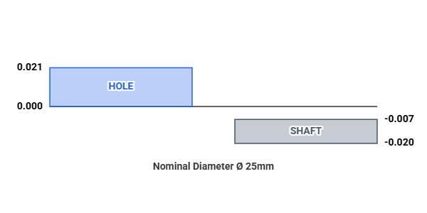
 - An example calculation can be found below already which is based on H7/g6 clearance, 25mm Nominal shaft and hole diameter and preference to modify shaft (hole basis).
How much clearance do you need?
Nominal diameter of hole and shaft (mm)
What part would you prefer to modify to achieve clearance?
Calculation Results
| Calculated Results | Hole | Shaft |
|---|---|---|
| Diameter Lower Limit (mm) | 25.000 | 24.980 |
| Diameter Higher Limit (mm) | 25.021 | 24.993 |
| Tolerance Lower Limit (µm) | 0 | -20 |
| Tolerance Higher Limit (µm) | +21 | -7 |
| Tolerance Code | H7 | g6 |
| CLEARANCE: 0.007 to 0.041 mm | ||
| Parts will always slide. | ||
Tolerance Diagram
Require different units not displayed?
CONVERT VARIOUS UNITS HERE